
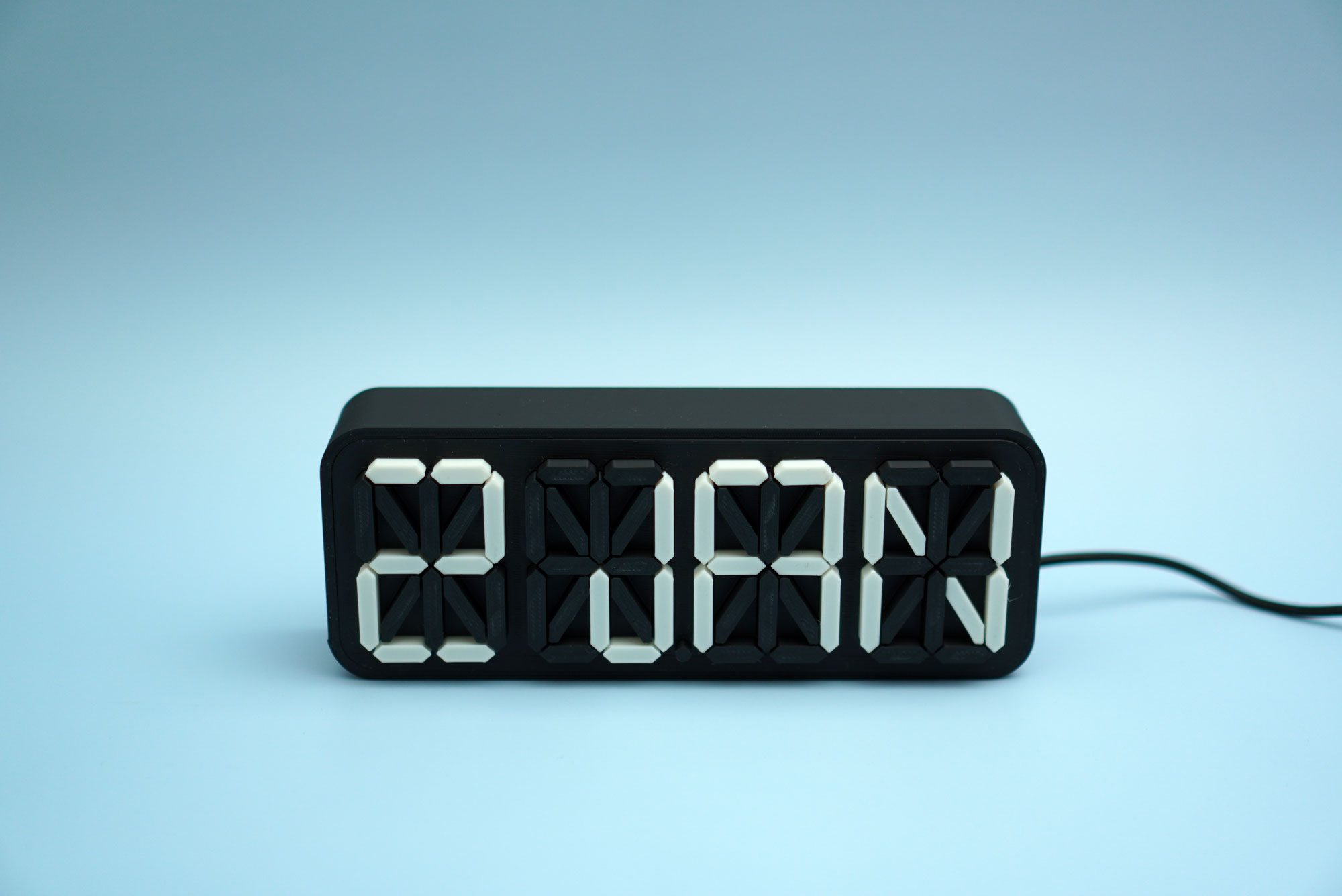
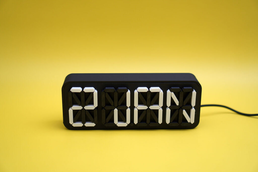
In this tutorial, I’ll be showing you how to make a 3D printed light box. At the end of the tutorial, you’ll be able to make something like this 16-segment display light box:
This tutorial requires you to use the software Autodesk Fusion 360 but there is a free version of the software for personal use that you can download, so it wouldn’t hurt to get it if you didn’t have the software installed on your computer yet. It’s a great software to have if you want to design technical parts.
Table of Contents
So before we get started, these are the materials and software that you’ll need:
- An LED strip
- PLA filament of 2 different colors; preferably white and black
Step 1: Creating an SVG file
First, we need an SVG file of the 16-segment display pattern. If the file is an image file (either .JPEG or .PNG), we can convert it to SVG using this website.
Just upload your file, choose SVG from the drop-down menu and hit convert. After it’s done coverting your file, download it to your computer.
Next, we are going to import the file into Fusion 360.
Step 2: Display panel
Importing the SVG file
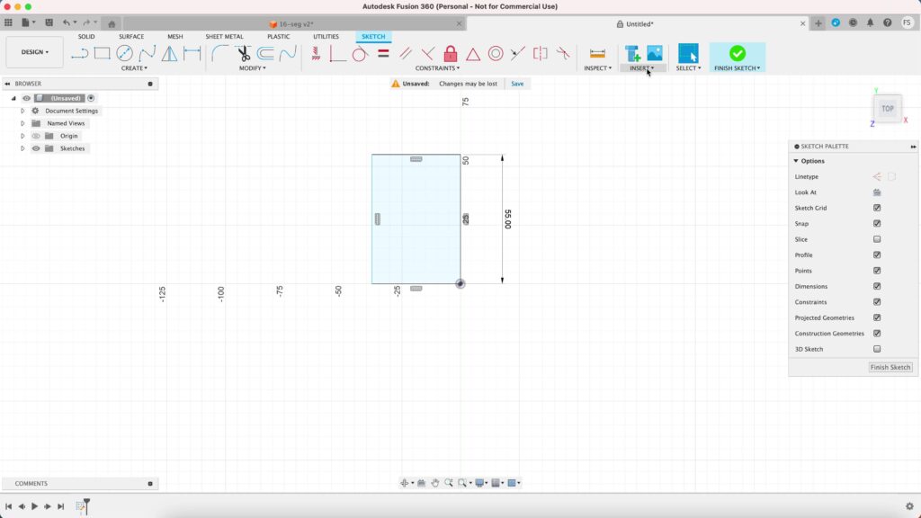
Let’s open our Fusion 360. Before we start, let’s create a rectangle. This rectangle will just be a reference for the height of our 16 segment display. Lets make a rectangle with the height of 55 mm (width doesn’t matter).
Click create sketch. You’ll then be prompted to choose any of the 3 planes. You can select any plane you want, but I like to start with the XZ plane as the base for my project.
Click the rectangle tool and draw a rectangle of that size to the left of the origin.
Now we want to import our SVG file of the 16 segment display, so lets hover to the top bar and click Insert, then select Insert SVG. Choose the file from your computer’s directory where you saved it and hit OK.
If you don’t see the file, it’s probably too big so just resize it. While you’re at it, resize the image so the height would almost fit the height of the rectangle. Click OK when you’re done.
Delete the rectangle since we won’t be needing it anymore.
Notice that the outlines are green? That means that the segments are constrained. We need to change the lines to blue so we can edit them, maybe move them around, alter their shapes, etc.
So to do that, select the whole image, then click the lock icon.
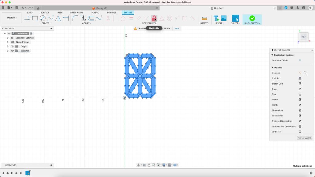
That will change all the outlines to blue and make everything easier to work with.
Let’s change the position of the image. Hightlight the whole image, right click on it and select Move/Copy. Set the X distance to 6 mm and Y distance to 5 mm and hit OK. Once that’s done, we are ready for the next step.
Creating offset
Let’s create the offsets. Click the Offset icon select any segment. You can then define the thickness of the offset, which is entirely up to you, but let’s it 1.0 mm. You want the offset to be on the inside of the segment, so type in -1.0 mm instead.
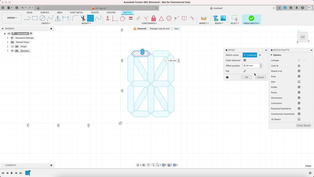
Then continue making the offset for the rest of the segments.
Creating duplicates
Next, we want to create duplicates. Our light box will have four 16 segment displays, so we need to copy our image and paste it three times.
I designed the box to be big enough to fit plate of my A1 Mini 3D printer. If you have a bigger printer that has a bigger print volume, you can make the box bigger or you can add more displays rather than just four.
Highlight the image, right click on it and select Copy. Alternatively, you can just hit Cmd + C (or Ctrl + C on PC). Hit Cmd + V (or Ctrl – V) to paste the image next to it. Move it 43.50 mm to the right of the X-Axis. Repeat this process until you end up with four images.
Draw a small circle at the bottom, right the middle of the entire sketch. Make sure not to forget to create an offset for this small circle too. Set the offset to -0.8 mm.
Creating an offset plane
Now let’s create an offset plane. This plane will actually be important in Step 2 when we’ll make the caps for the displays, but let’s make it now we don’t need to worry about it later.
While you’re in the sketch window, copy one image together with the small circle. Don’t worry about pasting it yet, we’ll get to that just in a minute.
Now click Finish to finally exit the sketch window and click Construct. Select Offset Plane and click any blue area of our sketch. Set the distance to 40 mm.
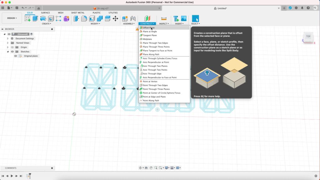
This will create a new plane, 40 mm away from our initial sketch plane. It can get pretty confusion later when you want to create the caps, so it is a good idea to work on them in a totally seperate plane.
The new plane is shown as an orange rectangle, so right click on it and select Create Sketch. You’ll now enter a new sketch window on your newly created plane. Now is the time to hit Cmd + V (or Ctrl + V) to paste what you copied earlier.
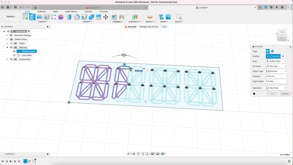
Creating the panel
Let’s head back to our intial sketch. Hide the new sketch first so it won’t get in the way. Right click the first sketch and select Edit Sketch.
Draw a rectangle, starting from the origin. Make the height 65 mm and the width 181 mm. This will be the size of our panel. Hit Finish to exit the sketch window.
Now lets turn our 2D sketch into a 3D object. Click Extrude and select the outlines of all the segments including the outline of the small circle. Set the distance to 5 mm and hit OK.
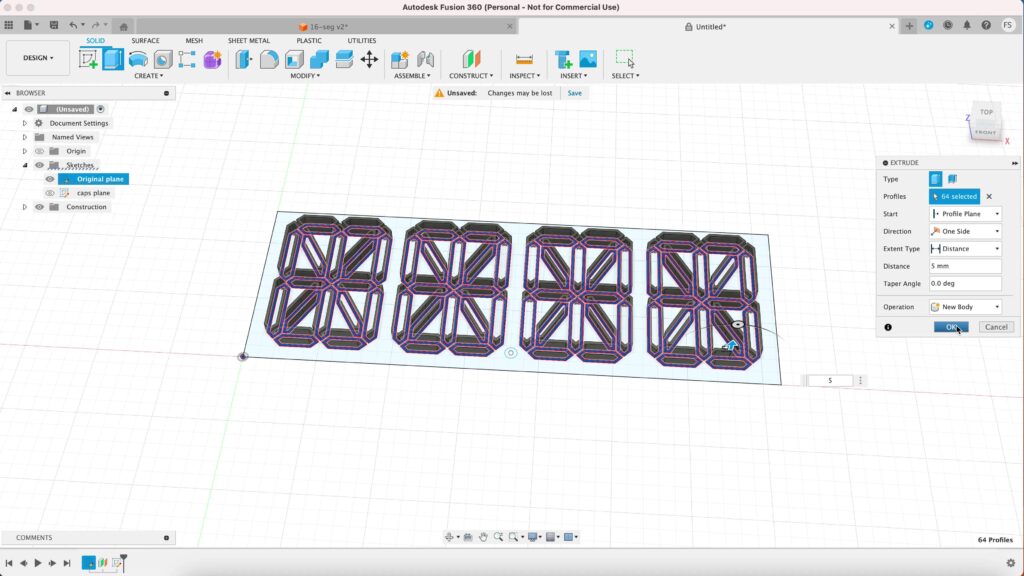
Now click extrude again and extrude the rectangle 10 mm up. Make sure to set the Operation to Join. This will join everything into one single part.
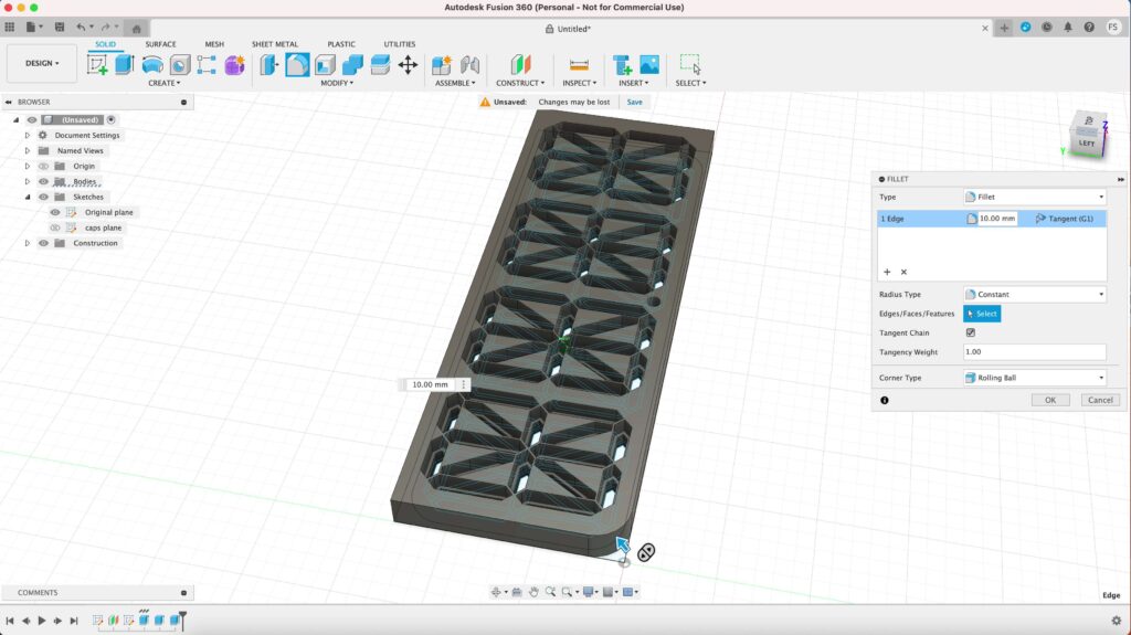
Now we’re actually done with our panel, but if you want, you can round the edges by using the Fillet tool. Click the Fillet icon, and select the vertical line of the edge. I’ll set that to 10 mm. Repeat the same process to create rounded corner for all the other edges.
Step 2: Caps
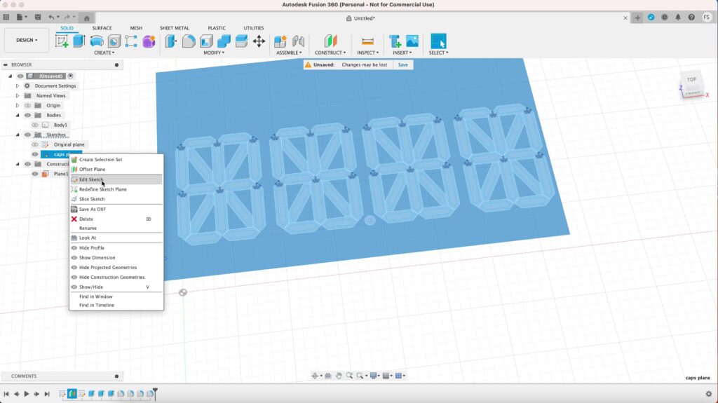
Now its time to create the caps. Lets move over to the sketch window in the offset plane.
Hide the 3D model of the panel first by clicking the eye symbol next to Body 1 under the Browser category Bodies. Right click on the sketch, and select Edit Sketch.
Creating offset
Lets create the caps for the segments. We don’t need to create the cap for all of them. We only need to create four caps plus one cap for the small circle.
The shapes of the segments repeat themselves, so for each shape, we only need to create one cap and then make duplicates of it in our slicer software later.
Create an offset for each of these following shapes:
- vertical segment |
- horitonzal segment –
- diagonal segment /
- diagonal segment \
- small dot •
Set the offset to -0.1 mm. We want the offset to be on the inside of the shapes. The purpose here is to make the caps slightly smaller (or offseting the outer surfaces to be exact) so it wouldn’t fit in the holes too snuggly.
One that’s done, you’re ready for the next step.
Creating the caps
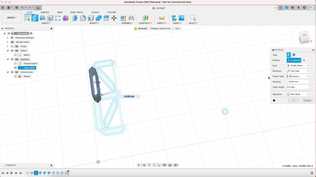
Now lets extrude the sketch to make the caps. Let’s start with selecting the outline of any segment. Make sure to exclude the most outer line of the sketch.
Extrude the sketch downward by typing in -10 mm.
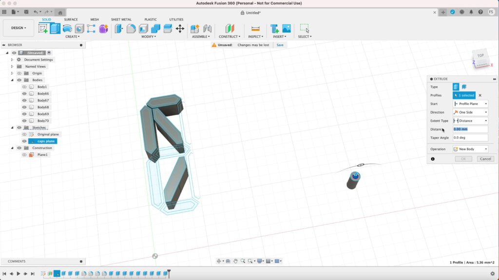
Next, extrude the most inner area of the segment. Set the dimension to -0.4 mm, and operation to Join. This will make the front face of the segment to be thin enough so the light can shine through it.
This will mean that the black caps will have a thin wall as well. But don’t worry, the light won’t shine through the black caps. Then proceed to making the caps for the rest of the segments.
Step 3: Light box
Let’s make the light box next and keep it simple so it’s easier to sketch and to print. Hide any parts that you don’t want to see. Right click on the initial sketch and select Edit Sketch.
Creating offsets
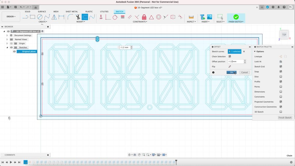
Let’s start with creating the first offset of the big rectangle. Set the offset to 3 mm. Next, create another offset and set it to -1.2 mm and hit Finish sketch.
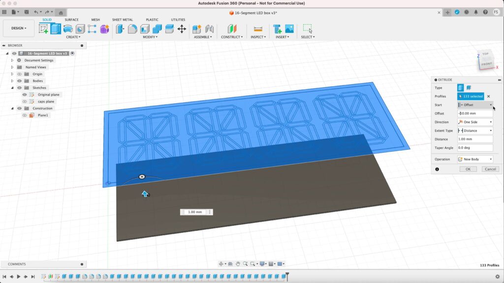
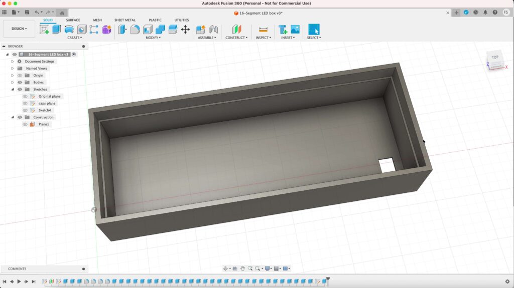
Lets extrude everything, including the segments. We can actually create a new sketch in a new plane, but i’m going to show you how you can do it on the exact same plane.
Click extrude. Now you want to change Start to Offset. Type in -50 mm and set the distance to 1 mm. This will create a new body 50 mm away from the initial plane. Click OK.
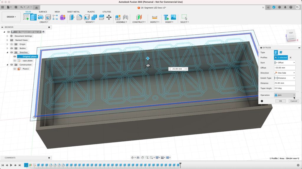
Next, click extrude again select the the outermost outline. We also want to offset the extrusion to -50 mm and set the dimension to 35 mm. Don’t forget to set the operation to Join.
Then extrude the inner outline, offsetting it to -50 mm as well and set its dimension to 25 mm. Set the operation to Join.
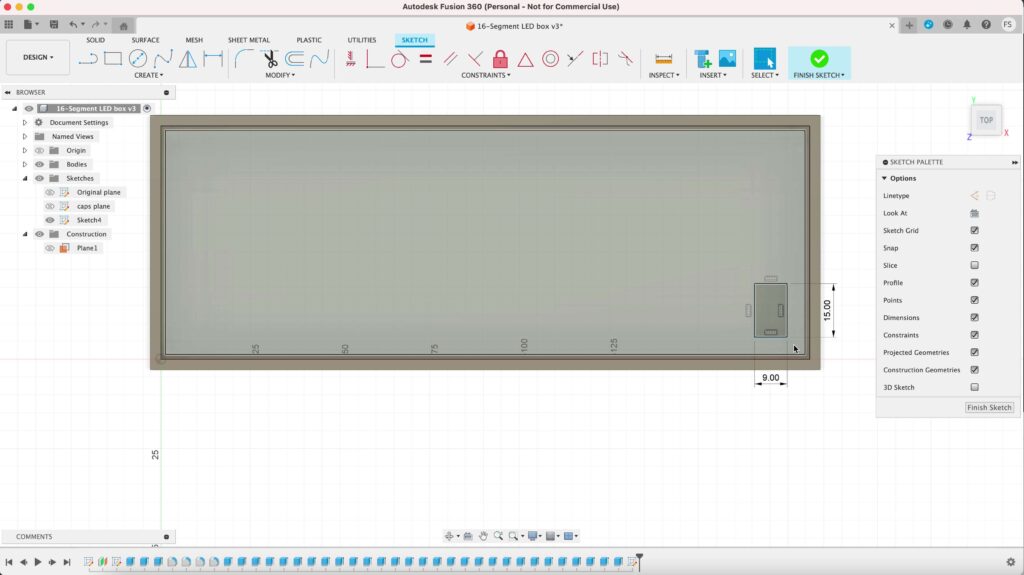
Making a hole
Since the box will house the LED strip, we want to make a hole on the backside of the box, big enough so you can pass through an LED strip through it.
Hide the sketch above it and click the bottom of the box. Right click on it and select Create Sketch.
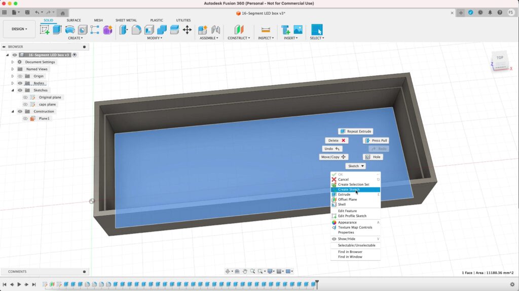
Draw a small 15 mm x 9 mm rectangle at the corner of the box. Extrude that rectangle away from the box and set the operation to Cut. This will cut a hole in the back wall of the box.
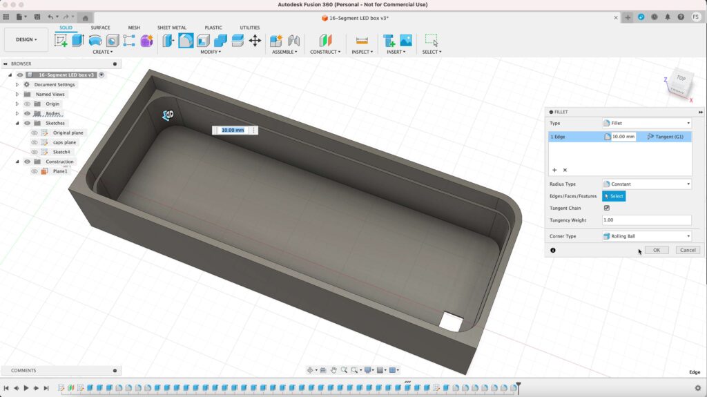
Rounding corners
Once you’re done, the last thing to do ist to round the corners. Set the the radius of the inner corners to 10 mm, and 12.5 for the outer corners.
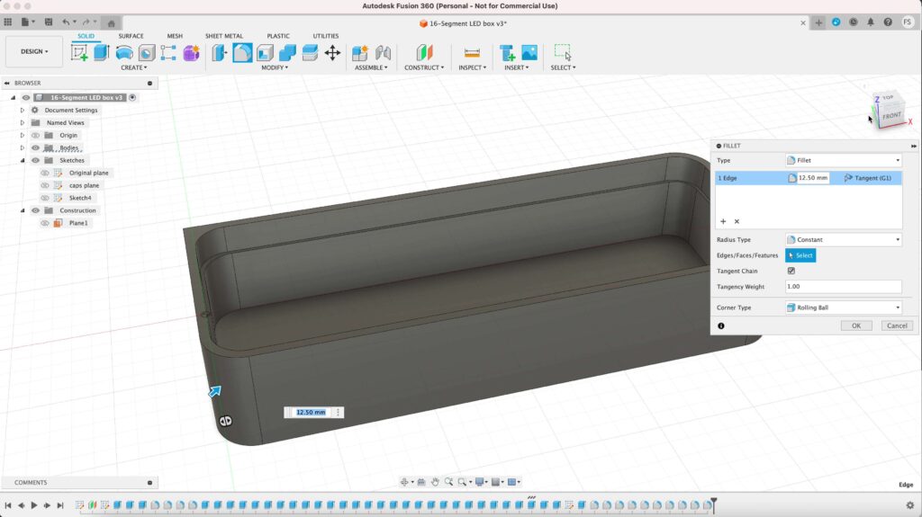
Now we are finished creating the box!
Step 4: Export as STL
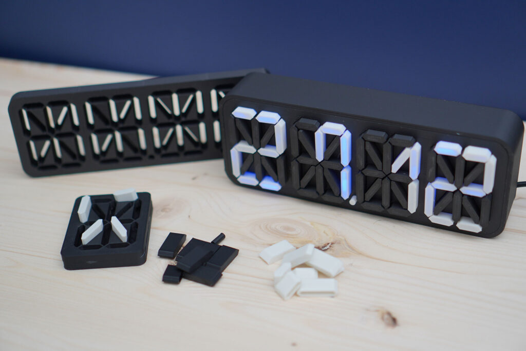
Export the parts individually as STL files. If you’ve done everything correctly, there are 7 parts in total:
- Panel
- Vertical segment cap
- Horizontal segment cap
- Diagonal segment cap
- Diagonal segment cap (mirrored)
- Small circle cap
To export a part in STL, select it (body), right click on it and select Save as Mesh. Set the format to STL (Binary) and save it to your computer.
Once you have saved everything, we are ready to open them in our slicer software.
Step 5: Print
Print the files with your 3D printer. Since i’m using an A1 Mini 3D printer, i need to print all of them seperately.
For the caps, you need to create duplicates. In Bambu Studio, it’s as simple as hitting the key combo Cmd+C and Cmd+V (Ctrl+C and Ctrl+V on PC). These are the amount of duplicates you need to create:
- Vertical segment cap: 24
- Horizontal segment cap: 24
- Diagonal segment cap: 8
- Diagonal segment cap (mirrored): 8
- Small circle cap: no duplicates, just 1 is enough
Total: 65 caps
Keep in mind that you need to print the caps twice, since you’ll need 65 white caps and 65 black caps. I recommend printing them on a smooth plate.
If you’re using a BambuLab 3D printer, you can try these settings:
| Nozzle | 0.4 mm |
| Layer height | 0.2 mm (Standard) |
| Wall generator | Arachne |
| Support | No support needed |
| Brim | No brim needed* |
Step 6: Installing an LED strip
Instead of buying a white LED strip, get the RGB LED strip. RGB LED strips are normally not that expensive and you can even change the color of your LED lights. Some LED strips even let you change the color of the lights wirelessly.
If you have self-adhesive LED strip, just stick the strip on the inside of the box. Pass the strip through the holes, adhere and cut the excess if you have any.
If you want to shorten your LED strip, make sure to cut it here (where it shows the picture of a pair of scissors):
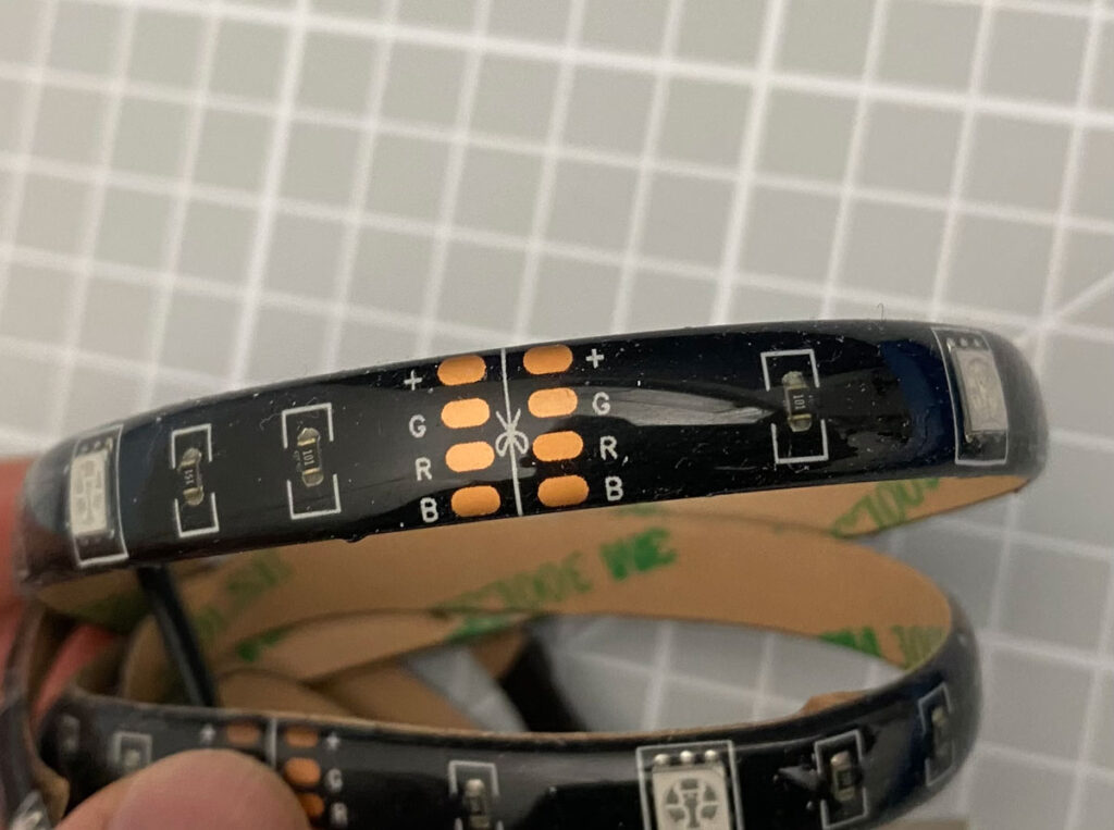
You probably would want to get a good quality LED strip. I made a mistake of ordering a cheap one and ended up getting an LED strip that doesn’t illuminate my light box much.
Then just place the panel on top of the box and you’re done!
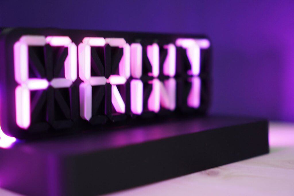
Using the same method, you could even make a similar light box e.g. a light box of your logo or even your name!
So i hope this tutorial is helpful and if you have any questions, just leave a comment and make sure to check out my other 3D print projects as well!

